| Chemistry |
Lithium Iron Phosphate (LiFePO4 / LFP) |
LFP chemistry provides strong thermal stability, long service life, and reliable performance for stationary storage, solar systems, and backup power. |
Confirm that every cell and the battery management system are designed for LFP chemistry rather than another lithium-ion formulation. |
| Nominal Voltage |
51.2 V nominal; commonly marketed as a 48 V battery |
A 16-series LFP battery uses 3.2 V nominal cells, resulting in approximately 51.2 V nominal voltage. |
Ensure the inverter, charger, DC distribution equipment, and low-voltage disconnect settings support a 51.2 V LFP battery. |
| Rated Capacity |
300 Ah |
Capacity determines how much charge the battery can store and influences runtime under a given load. |
Check whether the stated 300 Ah capacity is measured at a specified temperature, discharge rate, and end-of-discharge voltage. |
| Nominal Energy |
Approximately 15.36 kWh |
Calculated as 51.2 V × 300 Ah. This is the theoretical nominal energy before accounting for operating limits and efficiency losses. |
Compare usable energy rather than relying only on the nameplate kWh figure. |
| Usable Energy at 80% DoD |
Approximately 12.29 kWh before conversion losses |
Using 80% depth of discharge leaves about 20% state of charge and generally supports longer battery life than routinely using the full rated capacity. |
Confirm whether the manufacturer defines usable energy at 80% DoD, 90% DoD, or another operating window. |
| Cycle Life at 80% DoD |
Approximately 3,000–6,000 cycles |
Cycle life indicates how many qualified charge-discharge cycles the battery may complete before reaching its specified end-of-life capacity, often around 80% of initial capacity. |
Check the test temperature, charge and discharge rate, rest periods, end-of-life capacity, and whether the result is a laboratory value or a warranty commitment. |
| Continuous Discharge Current |
Commonly 150–300 A, depending on the BMS and cell design |
Higher continuous current supports larger inverter loads, but it also increases heat generation and may reduce available capacity at high load. |
Match the continuous current rating to the inverter's continuous DC input current, not only its AC output rating. |
| Recommended Continuous Load at 300 A |
About 15.36 kW at nominal voltage, before inverter losses |
Power can be estimated as voltage × current. Actual output may be lower because of voltage sag, temperature, BMS limits, and inverter efficiency. |
Verify the permitted current duration and thermal derating at high ambient temperatures. |
| Short-Term Peak Current |
Often 300–600 A for 1–5 seconds, depending on the BMS |
Peak current helps start motors, compressors, pumps, and other equipment with high inrush current. |
Compare the battery's peak-current time limit with the actual startup demand of the connected equipment. |
| Recommended Charge Current |
Typically 60–150 A; approximately 0.2C–0.5C for a 300 Ah battery |
Moderate charging rates can reduce heat and stress while providing practical recharge times. |
Check the maximum charge current allowed by both the battery BMS and the charger or inverter-charger. |
| Typical Full-Charge Voltage |
Approximately 56.8–58.4 V, subject to the battery manufacturer's settings |
LFP batteries require a compatible charging profile. Excessive voltage can cause BMS protection events or accelerate degradation. |
Use the exact absorption, standby, and equalization settings recommended for the specific battery. Routine lead-acid equalization is generally not suitable for LFP. |
| Low-Temperature Charging |
Charging is commonly restricted below 0°C; batteries with low-temperature protection may disconnect charging |
Charging an LFP battery below freezing can cause lithium plating and permanent cell damage. |
Look for an internal temperature sensor, low-temperature charge cutoff, heater option, or an installation location that remains above freezing. |
| Operating Temperature |
Typical discharge range: approximately −20°C to 55°C; charging range is usually narrower |
Available power, charging safety, and cycle life depend strongly on cell temperature. |
Confirm the exact charge and discharge temperature limits and any current derating at temperature extremes. |
| Battery Management System |
Required features: overcharge, over-discharge, overcurrent, short-circuit, over-temperature, and cell balancing protection |
The BMS protects the cells and controls safe operation under abnormal electrical or thermal conditions. |
Check balancing method, event logging, reset behavior, communication interface, and whether the continuous-current rating is truly 300 A. |
| Communication Interface |
CAN bus, RS485, or another inverter-compatible communication protocol |
Communication allows the inverter to receive state-of-charge, voltage, current, temperature, and protection information. |
Confirm protocol compatibility and cable pinout. A communication port alone does not guarantee compatibility with every inverter. |
| Round-Trip Efficiency |
Typically approximately 90%–96% at moderate power levels |
Higher efficiency reduces energy lost as heat during charging and discharging. |
Ask whether the published efficiency includes the BMS, cabling, inverter, standby consumption, and the selected operating power. |
| Parallel Expansion |
Often supports two or more batteries in parallel when approved by the manufacturer |
Parallel batteries can increase total energy and current capability for larger systems. |
Verify maximum parallel quantity, equal cable lengths, pre-charge requirements, firmware compatibility, and approved fuse or breaker ratings. |
| Protection and Disconnect Equipment |
DC-rated fuse or breaker, service disconnect, insulated terminals, and correctly sized conductors |
A 48 V-class battery can deliver very high fault current, so external protection is essential even when a BMS is installed. |
Use DC-rated equipment sized for the battery's maximum continuous and prospective fault current, following local electrical codes. |
| Approximate Weight |
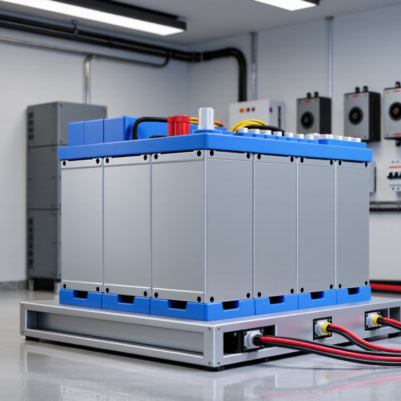
Commonly about 120–170 kg for a 15 kWh-class LFP battery, depending on enclosure and components |
Weight affects handling, floor loading, shipping, and installation requirements. |
Confirm the exact shipping weight, lifting points, rack or floor installation method, and required clearance. |
| Service-Life Expectations |
Often approximately 8–15 years in moderate-temperature applications, subject to usage and calendar aging |
Battery life is influenced by temperature, average state of charge, charge rate, discharge depth, and time spent at high voltage. |
Read the warranty conditions, throughput limits, minimum retained capacity, and exclusions for temperature or installation conditions. |
| Best-Fit Application |
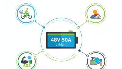
Solar energy storage, off-grid systems, backup power, telecommunications, and low-speed electric equipment |
The large capacity and high current capability suit applications requiring substantial daily energy or extended backup duration. |
Size the battery from the actual daily energy demand, peak power, backup duration, solar generation, and inverter efficiency. |